- 您现在的位置:买卖IC网 > Sheet目录629 > PAXCDL10 (Red Lion Controls)ANALOG OUTPUT CARD
�� �
�
�SENDING� SERIAL� COMMANDS� AND� DATA�
�When� sending� commands� to� the� meter,� a� string� containing� at� least� one�
�command� character� must� be� constructed.� A� command� string� consists� of� a�
�command� character,� a� value� identifier,� numerical� data� (if� writing� data� to� the�
�meter)� followed� by� a� the� command� terminator� character� *� or� $.� The� <CR>� is�
�also� available� as� a� terminator� when� Counter� C� is� in� the� SLAVE� mode.�
�Command� Chart�
�Command� String� Examples:�
�1.� Address� =� 17,� Write� 350� to� Setpoint� 1�
�String:� N17VM350$�
�2.� Address� =� 5,� Read� Count� A� value,� response� time� of� 50� -� 100� msec.� min.�
�String:� N05TA*�
�3.� Address� =� 0,� Reset� Setpoint� 4� output�
�String:� RS*�
�Command� Description�
�Notes�
�Transmitting� Data� To� the� Meter�
�N�
�T�
�V�
�R�
�P�
�Node� (Meter)� Address�
�Specifier�
�Transmit� Value� (read)�
�Value� change� (write)�
�Reset�
�Block� Print� Request�
�(read)�
�Address� a� specific� meter.� Must� be� followed�
�by� two� digit� node� address.� Not� required�
�when� address� =� 00.�
�Read� a� register� from� the� meter.� Must� be�
�followed� by� register� ID� character.�
�Write� to� register� of� the� meter.� Must� be�
�followed� by� register� ID� character� and�
�numeric� data.�
�Reset� a� register� or� output.� Must� be� followed�
�by� register� ID� character�
�Initiates� a� block� print� output.� Registers� are�
�defined� in� programming.�
�Numeric� data� sent� to� the� meter� must� be� limited� to� Transmit� Details� listed� in�
�the� Register� Identification� Chart.� Leading� zeros� are� ignored.� Negative� numbers�
�must� have� a� minus� sign.� The� meter� ignores� any� decimal� point� and� conforms� the�
�number� to� the� scaled� resolution.� (ie.� The� meter� ’s� scaled� decimal� point� position�
�is� set� for� 0.0� and� 25� is� written� to� a� register.� The� value� of� the� register� is� now� 2.5.�
�In� this� case,� write� a� value� of� 250� to� equal� 25.0).�
�Note:� Since� the� meter� does� not� issue� a� reply� to� value� change� commands,� follow�
�with� a� transmit� value� command� for� readback� verification.�
�Transmitting� Data� From� the� Meter�
�Data� is� transmitted� from� the� meter� in� response� to� either� a� transmit� command�
�Command� String� Construction�
�The� command� string� must� be� constructed� in� a� specific� sequence.� The� meter�
�does� not� respond� with� an� error� message� to� invalid� commands.� The� following�
�procedure� details� construction� of� a� command� string:�
�(T),� a� print� block� command� (P)� or� User� Function� print� request.� The� response�
�from� the� meter� is� either� a� full� field� transmission� or� an� abbreviated� transmission.�
�The� meter� response� is� established� in� Module� 7.�
�Full� Transmission�
�1.� The� first� characters� consist� of� the� Node� Address� Specifier� (N)� followed� by� a�
�2� character� address� number.� The� address� number� of� the� meter� is� programmable.�
�If� the� node� address� is� 0,� this� command� and� the� node� address� itself� may� be�
�omitted.� This� is� the� only� command� that� may� be� used� in� conjunction� with� other�
�commands.�
�2.� After� the� optional� address� specifier,� the� next� character� is� the� command�
�character.�
�3.� The� next� character� is� the� Register� ID.� This� identifies� the� register� that� the�
�command� affects.� The� P� command� does� not� require� a� Register� ID� character.�
�It� prints� according� to� the� selections� made� in� print� options.�
�4.� If� constructing� a� value� change� command� (writing� data),� the� numeric� data� is�
�sent� next.�
�5.� All� command� strings� must� be� terminated� with� the� string� termination�
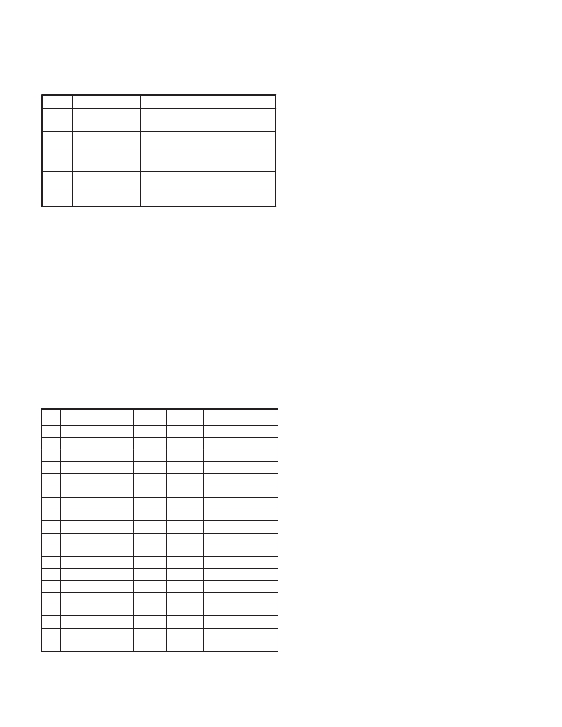
�Byte�
�1,� 2�
�3�
�4-6�
�7-18�
�19�
�20�
�21�
�22�
�23�
�Description�
�2� byte� Node� (Meter)� Address� field� [00-99]�
�<SP>� (Space)�
�3� byte� Register� Mnemonic� field�
�12� byte� numeric� data� field:� 10� bytes� for� number,� one� byte� for� sign,� one�
�byte� for� decimal� point�
�<CR>� (Carriage� return)�
�<LF>� (Line� feed)�
�<SP>� (Space)� ?�
�<CR>� (Carriage� return)� ?�
�<LF>� (Line� feed)� ?�
�These� characters� only� appear� in� the� last� line� of� a� block� print.�
�characters� *,� $� or� when� Counter� C� is� set� for� slave� mode� <CR>.� The� meter�
�does� not� begin� processing� the� command� string� until� this� character� is� received.�
�See� Timing� Diagram� figure� for� differences� between� terminating� characters.�
�?�
�The� first� two� characters� transmitted� (bytes� 1� and� 2)� are� the� unit� address.� If� the�
�address� assigned� is� 00,� two� spaces� are� substituted.� A� space� (byte� 3)� follows� the�
�Register� Identification� Chart�
�REGISTER�
�ID� VALUE� DESCRIPTION�
�NAME� 1�
�A� Count� A� CTA�
�COMMAND�
�T,� V,� R�
�2�
�TRANSMIT� DETAILS�
�6� digit� (V),� 8� digit� (T)�
�3�
�unit� address� field.� The� next� three� characters� (bytes� 4� to� 6)� are� the� register�
�mnemonic.� The� numeric� data� is� transmitted� next.�
�The� numeric� field� (bytes� 7� to� 18)� is� 12� characters� long.� When� the� requested�
�value� exceeds� eight� digits� for� count� values� or� five� digits� for� rate� values,� an� *�
�(used� as� an� overflow� character)� replaces� the� space� in� byte� 7.� Byte� 8� is� always� a�
�These� characters� only� appear� in� the� last� line� of� a� block� print.�
�B�
�C�
�D�
�E�
�F�
�G�
�H�
�Count� B�
�Count� C�
�Rate�
�Min�
�Max�
�Scale� Factor� A�
�Scale� Factor� B�
�CTB�
�CTC�
�RTE�
�MIN�
�MAX�
�SFA�
�SFB�
�T,� V,� R�
�T,� V,� R�
�T,� V�
�T,� V,� R�
�T,� V,� R�
�T,� V�
�T,� V�
�6� digit� (V),� 8� digit� (T)�
�6� digit� (V),� 8� digit� (T)�
�5� digit,� positive� only�
�5� digit,� positive� only�
�5� digit,� positive� only�
�6� digit,� positive� only�
�6� digit,� positive� only�
�space.� The� remaining� ten� positions� of� this� field� (bytes� 9� to� 18)� consist� of� a� minus�
�sign� (for� negative� values),� a� floating� decimal� point� (if� applicable),� and� eight�
�positions� for� the� requested� value.� The� data� within� bytes� 9� to� 18� is� right-aligned�
�with� leading� spaces� for� any� unfilled� positions.�
�The� end� of� the� response� string� is� terminated� with� <CR>� (byte� 19),� and� <LF>�
�(byte� 20).� When� a� block� print� is� finished,� an� extra� <SP>� (byte� 21),� <CR>� (byte�
�22),� and� <LF>� (byte� 23)� are� used� to� provide� separation� between� the� transmissions.�
�Abbreviated� Transmission�
�?�
�I�
�J�
�K�
�L�
�M�
�O�
�Scale� Factor� C�
�Count� Load� A�
�Count� Load� B�
�Count� Load� C�
�Setpoint� 1�
�Setpoint� 2�
�SFC�
�LDA�
�LDB�
�LDC�
�SP1�
�SP2�
�T,� V�
�T,� V�
�T,� V�
�T,� V�
�T,� V,� R�
�T,� V,� R�
�6� digit,� positive� only�
�5� negative� /� 6� positive�
�5� negative� /� 6� positive�
�5� negative� /� 6� positive�
�5� negative� /� 6� positive�
�5� negative� /� 6� positive�
�Byte�
�1-12�
�13�
�14�
�15�
�16�
�17�
�Description�
�12� byte� data� field,� 10� bytes� for� number,� one� byte� for� sign,� one� byte�
�for� decimal� point�
�<CR>� (Carriage� return)�
�<LF>� (Line� feed)�
�<SP>� (Space)� ?�
�<CR>� (Carriage� return)� ?�
�<LF>� (Line� feed)� ?�
�Q�
�S�
�U�
�W�
�X�
�Setpoint� 3�
�Setpoint� 4�
�Auto/Manual� Register�
�Analog� Output� Register�
�Setpoint� Register�
�SP3�
�SP4�
�MMR�
�AOR�
�SOR�
�T,� V,� R�
�T,� V,� R�
�T,� V�
�T,� V�
�T,� V�
�5� negative� /� 6� positive�
�5� negative� /� 6� positive�
�0� -� auto,� 1� -� manual�
�0� -� 4095� normalized�
�0� -� not� active,� 1� -� active�
�The� abbreviated� response� suppresses� the� address� and� register� mnemonics,�
�leaving� only� the� numeric� part� of� the� response.�
�Meter� Response� Examples:�
�1.� Address� =� 17,� full� field� response,� Count� A� =� 875�
�17� CTA� 875� <CR><LF>�
�1.� Register� Names� are� also� used� as� Register� Mnemonics� during� full� transmission.�
�2.� The� registers� associated� with� the� P� command� are� set� up� in� Print� Options� (Module� 7).�
�3.� Unless� otherwise� specified,� the� Transmit� Details� apply� to� both� T� and� V�
�Commands.�
�25�
�2.� Address� =� 0,� full� field� response,� Setpoint� 2� =� -250.5�
�SP2� -250.5<CR><LF>�
�3.� Address� =� 0,� abbreviated� response,� Setpoint� 2� =� 250,� last� line� of� block� print�
�250<CR><LF><SP><CR><LF>�
�发布紧急采购,3分钟左右您将得到回复。
相关PDF资料
PAXLC800
COUNTER 8-DIGIT BI-DIR COUNT
PAXLPT00
METER PROCESS TIME 6-DIGIT
PAXLR000
METER RATE INDICATION 6-DIGIT
PB52233SLK
PROJ BOARD COLDFIRE M52
PD412411
DIODE MOD ISO DUAL 2400V 1100A
PF24-30
TRANSFORMER LO PRO 15VAC 1.6A
PFT12-28
TRANSFORMER 16VCT 28VCT 12VA
PFT12-35
TRANSFORMER 16VCT 35VCT 12VA
相关代理商/技术参数
PAXCDS10
功能描述:DUAL POINT RELAY OUTPUT CARD RoHS:是 类别:继电器 >> 配件 系列:PAXCDS 其它有关文件:Declaration of Conformity 标准包装:1 系列:- 附件类型:散热片 技术规格:3.5° C/W 适用于相关产品:Multiple 系列 颜色:-
PAXCDS20
制造商:Red Lion Controls 功能描述:Card, Plug-In; + 0.01% 10 ms; Quad Setpoint Relay Output Card; PAX Series 制造商:Red Lion 功能描述:Bulk 制造商:Red Lion Controls 功能描述:QUAD RELAY CARD 制造商:Red Lion Controls 功能描述:OUTPUT MODULE RELAY 制造商:Red Lion Controls 功能描述:OUTPUT MODULE, RELAY 制造商:Red Lion Controls 功能描述:QUAD SETPOINT RELAY OUTPUT INTERFACE CARD; Accessory Type:Quad Setpoint Relay Output Interface Card; For Use With:Red Lion PAX Digital Input Panel Meters ;RoHS Compliant: Yes
PAXCDS30
制造商:Red Lion Controls 功能描述:Panel Meter, OptionCard for Dual Rate Totalizer, Quad Setpoint Sinking Output 制造商:Red Lion Controls 功能描述:QUAD NPN-OC CARD
PAXCDS40
制造商:Red Lion Controls 功能描述:Card, Plug-In; + 0.01% 10 ms; PAX Series 制造商:Red Lion Controls 功能描述:QUAD PNP-OC CARD 制造商:Red Lion Controls 功能描述:SOURCING OPEN COLLECTOR OUTPUT INTERFACE CARD; Accessory Type:Quad Setpoint Sourcing Open Collector Output Interface Card; For Use With:Red Lion PAX Digital Input Panel Meters ;RoHS Compliant: NA
PAXCK000
制造商:Red Lion Controls 功能描述:Timer; Red, Sunlight Readable; 0.56 in.; 18 VA; 85 to 250 VAC; 2300 V (RMS) 制造商:Red Lion Controls 功能描述:CLOCK/TIMER FIELD UPGRADEABLE 制造商:Red Lion Controls 功能描述:DIGITAL MULTIFUNCTION TIMER RTC 制造商:Red Lion Controls 功能描述:DIGITAL MULTIFUNCTION TIMER, RTC 制造商:Red Lion Controls 功能描述:DIGITAL MULTIFUNCTION TIMER; Supply Voltage Range:85V AC to 250V AC; Time Min:0.001s; Time Max:1h; Power Consumption:18VA; Panel Cutout Height:45mm; Panel Cutout Width:92mm; Character Size:0.56"; Display Font Color:Red ;RoHS Compliant: NA 制造商:Red Lion Controls 功能描述:DIGITAL MULTIFUNCTION TIMER, RTC; Supply Voltage Range:85V AC to 250V AC; Time Min:0.001s; Time Max:1h; Power Consumption:18VA; Panel Cutout Height:45mm; Panel Cutout Width:92mm; SVHC:No SVHC (19-Dec-2012); Count Speed Max:50Hz; ;RoHS Compliant: Yes
PAXCK010
制造商:Red Lion Controls 功能描述:CLOCK/TIMER, FIELD UPGRADEABLE RED DC 制造商:Red Lion Controls 功能描述:DC CLOCK/TIMER FIELD 制造商:Red Lion Controls 功能描述:DIGITAL MULTIFUNCTION TIMER RTC 制造商:Red Lion Controls 功能描述:DIGITAL MULTIFUNCTION TIMER, RTC 制造商:Red Lion Controls 功能描述:DIGITAL MULTIFUNCTION TIMER; Supply Voltage Range:11V DC to 36V DC; Time Min:0.001s; Time Max:1h; Power Consumption:14W; Panel Cutout Height:45mm; Panel Cutout Width:92mm; Character Size:0.56"; Display Font Color:Red ;RoHS Compliant: NA
PAXCK100
制造商:Red Lion Controls 功能描述:CLOCK/TIMER, FIELD UPGRADEABLE GREEN 制造商:Red Lion Controls 功能描述:CLOCK/TIMER FIELD UPGRADEABLE
PAXCK110
制造商:Red Lion Controls 功能描述:CLOCK/TIMER, FIELD UPGRADEABLE GRN DC 制造商:Red Lion Controls 功能描述:DC CLOCK/TIMER FIELD UPGRADEABLE